A Goban 9*9 - Part One
Having finished my
latest ship model I decided to try and make my own goban. I had an idea (taken from a model ship's deck)
that I thought had plenty of potential for making a nice board. Initially I
would try a 9*9 just to test the concepts out and get an idea of relative sizes
/ construction issues / measurement problems before potentially moving to the 19*19.
This post is
primarily concerned with some very detailed design & technology notes for the 9*9 board so unless you are particularly interested in Go boards it may be best to give these (and related posts) a miss.
Pre-Design
I tend to rough
draft design concepts before producing scaled drawings so drew some horrible
pencil scribbles sketching out the key concepts and some potential jigs that
may be needed for the full size board. I also decide at this point how engineered it
will be and as I do not expect the board to be mishandled I will not be putting
in too many damage prevention measures. If I had followed this path then I
would probably dowel through all the various components so they cannot move. As
it stands they will be glued together and then sit on a base board.
The other pre-design
information I needed was in how thick it would be - as I had some pear planks
spare at a thickness my table saw could (just) cope with I just selected this. More importantly I needed to know how thick a cut the saw would make. This is not a fixed amount as I
can buy different blades of different widths but for home use I was not to concerned at matching the traditional numbers. For reference the lines on the
go board are apparently 1mm wide. My table saw cuts at 1.5mm wide so it will be
slightly wider but not enough to be ridiculous.
Initial Design Stage
For the primary
design I use TurboCad which is not too expensive and does a good job once you understand how to use it. My
essential idea is to build the board in sections and then cut the lines into
it. These lines will then get filled (caulked in naval terms) with a dark
brown/black filler before the top is planed down a few millimetres. The nice
thing is that if the board is ever damaged a re-plane and varnish will
completely re-surface it giving it potentially a long lease of life.
The CAD program is
very useful here in getting measurements exact and when you are using power
tools to cut exactness is very important. I am planning on using Chinese Junzi
Stones (from Hoyles here) as my stone of choice so am also using Chinese
measurements for the board which are slightly larger than the Japanese
equivalent.


the initial board plans.
Beyond how the board
would be designed and built my other choice was how the board surround would be
made. Here I decided on a Lap Joint as the board would not be oversized and the
joint would be wrapped around the board itself so would be quite strong. No need
to over engineer at this point.
Board Preparation
I find when working
with wood that you need to know which dimensions need to be exactly the correct
size and which require a few mm extra. I therefore started by cutting some
wood blanks and thicknessing them down to the same size. What size was unimportant
as the board would be planed on completion but it needed to be the same to make
the line cut depths the same (again not actually important but attempting accuracy everywhere helps improve accuracy when it is most needed).

Once the boards were the same thickness I cut the blanks for the board producing another couple of 'spares' for miscut and practice reasons.

cutting to the correct width using the fence
Once the boards were the same thickness I cut the blanks for the board producing another couple of 'spares' for miscut and practice reasons.
This is an ideal job
for my table saw and I cut them a millimetre oversize. I also used the fence
and a push stick and not the cross cut tool. You may be tempted to use both but
try not to. Most saws rely on pressure on one axis so you should either use the
cross cut OR the fence. Using both tends to cause the blade to trap and nasty
things like kick back to occur though this is more an issue with a 'big' cut and less with something small.


my lovely thicknesser
To complete I then used
the table saw to get the lengths correct. I would have preferred to use a disc
sander for this as I have more control but with this size of wood and having to sand end grain you will find
most disc sanders will burn rather than sand the wood. A table saw is not ideal
for this but as a process I made one piece then put that end to end with the
next and laid the correctly sized piece against the blade which overlapped the
incorrectly sized piece. This allow all the pieces to be (hopefully) the same
length. When making similar pieces it is often safer to use other pieces to set sizes than re-measuring each time.

the blanks cut and ready
Once cut I then used
my thicknesser to bring the pieces back to the exact required width. I could
now work out the order each piece would go in and once done marked the piece id
on the bottom and an X at one end. Both are important as minor errors can be introduced by flipping a piece mid cut without realising - especially with this tool kit approach to building the board.


sized and thicknessed
Notes on Measuring
For measurement I used multiple tools as you should always endeavour to measure twice and cut once. My primary rulers are steel as this is less susceptible to warping than plastic/wood and when using rulers a useful tip is to measure from the 10 (or other mid number) than than the 0 as the start point can be misjudged. I also have an excellent tool for measuring very accurately below 25mm and finally callipers for larger. The key with the last two is to ensure that the piece can move semi-freely. If it is 'gripped' then the measure shown is actually too small and the tool is gripping and not measuring.


some of the key measuring tools
Cutting the Lines
This was the first
nerve wracking operation due to the high potential to muck things up. Therefore I
tested all cuts with some of my extra pieces first to validate measurements and
concepts before moving onto the prospective board pieces.
The first cut to do
was the end cut. The table saw blade was put to full height and I placed a
blank between the blade and fence and pushed that through. This ensured the
blank was exactly the width to be next to the blade but not to be cut by the blade. I
then dropped the blade to 6mm high and used the cross cut tool (note I am
breaking the rule above but was only using the blank next to the fence as a
support not for pressure) to cut the end lines. Since the blade is only slightly above the table it is also considerably stronger at cutting than it would otherwise be with less potential for the blade bending into the cut due to pressure or grain etc.


cutting the end cut
For the side (one
piece has cuts both long sides and all the others have a single long cut) I
dropped the cross cut tool which can not cope with length and used the blank as
the guider and my hands. Since the cut is much less than the wood depth it is
relatively safe but it is a table saw so being very aware of the blade location
is always important. Not using too much downward pressure reduces the risk of
falling into it or scootting the piece forward and doing the same.


the horizontal and end cuts all done
I was happy with the
lines so far which cover the horizontal board lines but now needed to start on
the verticals and these are more challenging. For the full board this will need
a jig to do so accurately (and I have an idea for this but for the 9*9 I could work with blanks and it should
come together.
Again using the
fence for support but the cross cut tool for grip and control I measured out
the required gap and ensuring the X was touching the fence and cut out the first
line. I then repeated the cut for all the other pieces (eventually I flipped
the piece and repeated for the other side as well - the lengths absolutely need to be near identical for this!). Once cut one was done I cut
out several wood blanks at the one gap setting on some scrap wood and then I
moved the fence before placing two of these together to get the rough next slot
location. Cutting into a test piece and measuring the gap and then adjusting
accordingly with my micrometer stop got the gap better placed before I could then repeat. Each time
ensuring the piece was face down (piece number on top) and the X was at the
correct end. This worked for cut three as well leaving the central cut. This
required some measurement and adjustment to get located but once set it was
simple enough to cut through.
Then the money
moment of lining them up to see if they matched. Any discrepancy would be
horribly obvious especially with incremental errors. Fortunately there did not
seem to be any visible ones so I could move on.


Along with the vertical cuts
Tidy Up
If not using a
slitting blade then wood cut in this fashion can be messy round the edges so I
needed to run a scalpel over the pieces to clean up any wood still sticking up.
Any edge damage will be tidied by the planing at the end but we want to avoid
the chance of a measurement issue due to wood damage. Scalpels are the sharpest and most delicate and controllable knives out there and years ago I purchased several hundred replacement blades from a medical supplier (note these are often not permitted for general sale so you have to give a good explanation as to 'why' and often buy more bulk than you may initially intend)
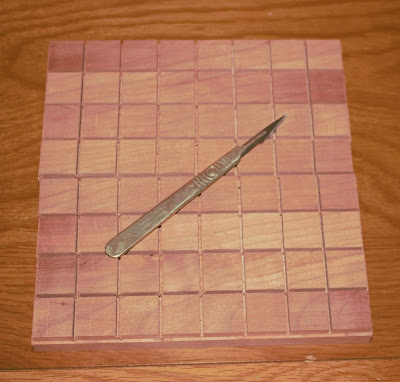

scalpel 'sharp'
First Glue
The next step is to
start gluing. Basically I need piece 2 glued to 3. 4 glued to 5 and 6 glued to
7. The reason here is that the board star points are in the middle of all these pieces and
it is safer and more accurate to drill them when they are one solid piece. For this step I
used wood glue thinly spread out (this may impact board dimensions slightly so
I am going to pay close attention to the end measurements - if it does as then
for the full board I will include the adjustments noted here inside the width/length calculations). I
then use a clamp with its pressure point NOT close to the cut marks (as this
would force the boards into a slight V warp which would not be insurmountable
but would be irritating to have to counteract). Two smaller V clamps were then planted at either end
to help prevent any tendency for a warp and to help ensure it was gluing as one
piece. I then left it all night to set. Glues differ on set requirements but this one needs two hours minimum clamping time followed by eight hours to set properly. Since I was not
reinforcing the structure with dowels I saw no need not to ensure the glue had the best
chance at strength so let it do its stuff.


clamps everywhere. plus they will get bigger as the project continues
Test Again
Now glued I then
re-checked everything was still flat and joined and was happy to see that it
still was. A good set square helps with this.

So that is it for Stage One. My next steps are to start working on the surrounding sections in more detail in TurboCad andthen to cut those out. This will be covered in a second post. The final post will cover the potentially disastrous caulking and planing to complete and is intended for a third post. I will cover any mistakes and cock ups more in detail in the last post. As an example just before writing this I managed to drill a test hole through one of my main pieces thinking it was a test piece so will have to spend tomorrow re-doing it. I will have to work out a way to avoid this in future (beyond not taking my stupid pills).
Thanks for reading!

one of my wonderful sons helping demonstrate checking the correct angles
So that is it for Stage One. My next steps are to start working on the surrounding sections in more detail in TurboCad andthen to cut those out. This will be covered in a second post. The final post will cover the potentially disastrous caulking and planing to complete and is intended for a third post. I will cover any mistakes and cock ups more in detail in the last post. As an example just before writing this I managed to drill a test hole through one of my main pieces thinking it was a test piece so will have to spend tomorrow re-doing it. I will have to work out a way to avoid this in future (beyond not taking my stupid pills).
Thanks for reading!


Comments
Post a Comment
What are your thoughts?